For my maker faire project I decided to work on a recoil based rocket engine model. The way a recoil based engine works is a cannon fires a round at the precise direction, and then, using Newton's Third Law, the rocket is pushed forward. I was inspired by a Kerbal Space Program video made by YouTuber Scott Manley about a joke rocket made out of four GAU-8s (the A-10 Thunderbolt II's gun) pointed downwards, that actually worked until the guns needed to cool down and the rocket came crashing back down. I expanded the idea to include a turret for pitch, yaw, and roll control. I realize that the objective of this prototype was for a more efficient rocket engine, and the discarding of stages efficiency due to each individual "stage" (bullet) being so small that the weight is discarded as thrust remains the same. I had a challenge where the "instance" command wasn't working in Blender and I had to switch to Tinkercad to fix the issue. If I were to do anything next it would be designing the firing mechanism and loading mechanism. The 3D model probably costed around $800 (including cost of 3D printer), but if you already have a printer, then around $2.
Scott Manley's video: https://www.youtube.com/watch?v=G1wgGRcmxIE (Go to 13:18 for the recoil rocket)
Showing posts with label 7th grade. Show all posts
Sonar Measuring Device
For my Maker Faire project, I wanted to make a cool electronic device. I heard about laser and sonar measuring devices, but the laser is very complex so I went with a sonar distance measuring device. This is a device that sends a very high pitched sound (higher than humans can hear) to a target and when the sound bounces back the device receives the sound and based on how long it took for the sound to come back it sends a certain pulse (a burst of electricity that lasts a certain time).
I coded my Microbit to convert that pulse into the distance based on an algorithm. The Microbit displays the distance to the nearest foot on the LED display. The Microbit was being powered by a battery pack and the Microbit was powering the sonar sensor and the sonar sensor was sending back out that electricity as a pulse, but there was a problem. Computers are made of 1s and 0s, which are represented by a voltage. X voltage and below would count as 0 and Y voltage to Z voltage would count as 1 (any above and the computer might fry) (X, Y, Z are random volts where X<Y<Z), but there is a gap between X and Y because any voltage in that gap might just be a vibration so . The pulse that the sonar sensor was sending was in that gap, so the Microbit couldn’t receive it. The sonar sensor was lowering down the voltage by 2 volts to the Microbit’s gap. So I got a mobile phone charger, which emitted more volts than the Microbit which is powered by batteries, connected it to a board and had two wires, one going to the Microbit and one going to the sonar. This phone charger gave the sonar a larger input than the batteries + Microbit, so the output (pulse) would be in the Microbit’s voltage range. But the pulse was above the Microbit’s range (an area where it would get fried), so I added three diodes which decreased the voltage to the 1 area so the Microbit would pick it up.
I had a really fun time making this. I learned from my dad about the range of 1 and 0 and the gap between which is really cool and I have a newfound respect for DIYers who use spare electronics to make things. In the future, I would like to make it more precise and accurate in its distance readings. I should say I want to make it all less messy or at least 3d print a case for it, but I know I don’t care enough about neatness to do so. If someone wants to do this I would recommend using an oscilloscope or something of that sort before plugging it into the Microbit because it is easy and not fun to fry it.
Estimated total cost: $45 (though the sonar sensor I already had from my dad’s old DIY drone, I had the Microbit, which I have used in previous projects, and the rest was stuff my dad had).
Links: https://www.maxbotix.com/Ultrasonic_Sensors/MB1000.htm, https://microbit.org/code/, https://www.maxbotix.com/documents/LV-MaxSonar-EZ_Datasheet.pdf
Talking Teddy Bear
Our goal was to create something that was both creepy and cool at the same time. We accomplished that by taking an old talking Teddy Ruxpin (a vintage talking teddy bear that used to be worth a lot), and gutted it, and put more modern motors in its head to move the eyes, nose, and mouth. If we had more time, we would have installed a raspberry pi with a special version of Alexa, along with the code to sync the movements of the mouth with the speech of Alexa. If we were to turn our project into something really creepy, we could have added a camera to the bear and added motion detection and facial recognition. We knew this was all possible and we had the materials and the know-how to build it, we simply just didn’t have the time.
Our inspiration to build this teddy bear was TinkerNut, a YouTuber who demonstrated that it was possible to give a teddy bear Alexa. We looked up to them for how to work on our project. They showed us lots of how we should build our teddy bear.
A challenge we encountered was mostly time restraint and getting the new motors to fit into our teddy bear. On the topic of time restraint, we had very big ideas and dreams of what our project would become, but we did not consider how little time we had to do it. We got over having trouble with the motors by starting with a new motor and ripping up the case less so it still fit in the socket.
We learned how to rip apart a Teddy Ruxpin and make it look extremely disturbing. We also learned how to put motors together and we learned a lot about how motors and circuits work.
We would advise to not procrastinate and not to plan to do something huge that will probably take more than your whole life span to finish (if you even live an average lifetime; we’ll probably die because of climate change soon enough. Or maniacal talking teddy bears. Lol… we're all gonna die...).
Our total cost: $120
Links:
https://www.youtube.com/watch?v=cwHS7F6L13E
https://www.youtube.com/watch?v=34cfkA9HlXk&t=184s
https://www.youtube.com/watch?v=AZX9rU9Sbhk
Automatic Chicken Feeder
Our project, the automatic chicken feeder, can be used for easier and more efficient chicken feeding. It will make the twice a day feeding as simple as pressing a button. We wanted to do this project because one of us is taking home four of the chickens we raised at school. He wanted to make his chicken related chores easier and less time consuming.
There were some challenges that we faced. The challenge that we faced the most was that the motor was not strong enough, or the containers movement was not stable. The motor we used was not strong enough to lift all the food, so we had to put it at a slant to distribute the weight across the feeder. The container was originally designed to push up the food and then it would fall out a hole, but when the container was pushed up, the container would fall over. We scrapped that idea and went with a wheel that would push out the food, and it was more feasible than the last idea.In the process of doing this project, we learned that dc motors are not the strongest and we needed to not put all the weight on the motor, or else it would not work.
Our next steps would be to build the feeder with plywood and nails, instead of cardboard, duct tape, and hot glue, and replace the DC motor with a stronger one. If someone else is going to build this, I would recommend them to use a more powerful motor than a DC motor.The cost was estimated to be about $16.50. This includes plywood for structure, the DC motor for the automatic part, a couple thin steel rods that can be used as axles. On the Paper Mech website, we found a simple machine to push up and down a platform, but that idea was eventually scrapped due to the platform not being stable. http://www.papermech.net/up-down-crank/
Bicycle Ice Cream
Bicycream
By: Margaux, Ermie and Theo
For BPC’s Maker Faire, 2019, our group decided to base our project around making ice cream while biking in place. Our project also incorporated the idea of the motivating people to work by having a sweet end goal in mind; the only way to obtain the reward of your exercising, the ice cream, is to bike and actually churn the ice cream by cycling. We decided to do this project because some people won’t exercise without a reward,or are lazy and need a way to motivate themselves. Now, we have found a solution to this problem: Ice cream. We discovered a way for someone to make ice cream while biking, and the only way to obtain this cool, refreshing treat is to go on a bike ride in your house while binging on your favorite Netflix show or around the park while enjoying the fresh air.
First, we envisioned a frame around the back wheel with a cylindrical box attached in the middle. The power would be generated by the back wheel. Since the container was touching the wheel while it spun, the container, in contact with the wheel, would spin as well. We didn’t prototype this idea, which was a mistake that ultimately made it harder to complete our finished project, but we did brainstorm for quite some time and figured out different ways to make it work.
To assemble all the pieces, we went to Ace Hardware to get a PVC cross-connector. We put the bike head through the cross and attached two pieces of PVC on either side of the seat. Then, we put a T-connector on both ends of the PVC so we could add two new longer pieces of PVC that extended all the way and rested near the back wheel. Finally, we attached the container to these pipes by drilling holes into either end sticking a wooden dowel through the lid and bottom. The dowel continued into the PVC pipes that were already drilled with holes. With the box in between the pipes, it rested on the wheel and spun with it.
This is what it looks like:
We were inspired to do this project because we had immediately known that we wanted to do something centered around ice cream, but were unsure of what. One of our group members had previously made ice cream in plastic bags and found it to be successful and easier than using an ice cream machine. We needed a simple and portable way to make it at school, so we thought of homemade ice cream in plastic bags. After presenting our ideas to the teacher, we decided that, even though it was a good project, we needed more. With that, we turned it into bicycle ice cream! The objective our our new-formed plan was to motivate people to exercise by giving them a reward to work for. They have to earn it; if they don’t pedal, there is no ice cream. We were stuck and couldn’t find anything to do for Maker Faire but our brilliant, smart, ingenious, creative science teacher, Ms. Mytko suggested we do something very "makery," like a thing that was powered by a bike. We also wanted to do something with ice cream so we combined the two ideas and created our project.
A challenge that we faced was getting the PVC to stay in place. As you can see in the photo above, a member of our group is holding the PVC pipes so that they would stay in place, but when no one was holding them it would slide off the wheel and bump around, therefore causing it to not turn as smoothly when we were pedaling. To solve this problem a member in another group suggested that we use wire and attach it to the bike itself, and after we tried this, it started to work a lot better. As a result, the ice cream did not slide around as much, and overall came out a better consistency. At first, I was reluctant because I wanted to base the project off of the bike exclusively. Eventually, we did it with the help of the other group members. It stayed in place pretty well even though we had to use the borrowed item to do so.
We learned many things on the way to creating our final, finished project. Among those many, the ones that stand out the most are adaptability, making things up on the fly, and that even if you mess up, there is always a way to fix it or make it better. We learned adaptability because our project started out as one simple thing that gradually changed, a lot at first, and then gradually over the course of our project. We learned that making up thing whilst in the middle of doing something, or figuring out that something doesn’t work, came in handy when we couldn’t get the container to stay put on top of the wheel. In the very beginning of our process, when we were drilling holes into the PVC pipes, we would keep either making them too big or too small. Whenever that happened, we would just start over, either on a new pipe or on the opposite end. These are skills that other people attempting to do similar projects would be better off learning earlier on.
If we had more time to complete the project, since we had a pretty good basic start to it, I think we would have just finessed it more, made it run more smoothly, and made larger quantities of ice cream to share with everybody. Our bike-powered ice cream machine worked, but it was only the base platform of what we could accomplish.
The estimated cost we have of our project is very low. Most of the materials we used we found in and around our school, or people had at home already and were fine with bringing them in for use. The only things people in our group purchased was a four-way PVC pipe connector, purchased at Ace Hardware for around $5, and a half gallon of half n’ half, purchased also for $5. Our total project cost was $10. The only outside resource we really used to base our ideas off of, a video as well as a website, was a great example of someone using bicycle ice cream for theirs, as well as other people’s benefits. They made ice cream on a hot, sunny summer day, went for a nice relaxing bike ride, and shared some homemade ice cream with friends and strangers. It was also just a great project in general, and surely inspire other makers to do the same and more.
https://www.youtube.com/watch?v=XbKHoCDwIOg
The Mighty Hug Machine
For our project, we designed a hug machine. We designed the machine so that if someone put an object in front of it, the machine would squeeze or hug it in a matter of a couple of seconds. We were not really inspired by any other projects, but we were inspired by lonely people who did not have hugs. Hugs can help calm people down, and everybody needs a warm embrace after a hard day. We just came up with the idea, along with a couple of other ideas, and after changing our project three times, decided to go with this one.
We had some problems with the design of the machine. The most prominent challenge we had was figuring out how to get the forearms of the machine to curve inwards in order to squeeze or hug the object or person. We spent a lot of time thinking about this issue until we finally came up with a solution. Our solution was to attach poles to the machine to block the movement of the forearms while the upper arms kept moving away from each other to make the forearms curve inwards into a hugging or squeezing position.
We used YouTube to research how to animate our hug machine 3D model using Blender. Although it took time and effort, we finally learned to animate using Blender, and to successfully create an animation of what our hug machine would have looked like.
Due to the time constraints, we were unable to construct a physical machine. If we had been given more time, we would have done so. We would also have tried to advance the design of the machine so it would also work with smaller objects or people. With our machine the way it is now, any object or person we used would have to be reasonably big.
We would advise people to focus on the brainstorming, since a good idea is essential to having a good project. While you obviously should not get carried away, do not be afraid to push yourself out of your comfort zone. We would also advise people to get an early start and to do most of the designing at the very beginning.
Our project cost $0 since we did not build it. If we had, it would have probably cost somewhere in the $150-200 range due to the amount of wood necessary to build the body of the machine, large servo motors to move the arms, and padding for the arms to make it more comfortable and less rough.
Bibliography
Studios, Thilakanathan, director. Introduction to Basic Animation in Blender. YouTube, YouTube, 25 Aug. 2015, www.youtube.com/watch?v=7ZkdR1L91Ik.
Labels:
7th grade,
Advice,
Animation,
Blender,
BPC Maker Faire,
cool project,
Electronics,
Motors,
school
The Useless Box
We made a Useless Box out of foam board, wood, and a circuit. As the name suggests, it literally does nothing. You flip the switch at the top of the box and a wooden arm will come out of the box to flip it back. Its sole "purpose" is to turn itself off. Our objective was to create a useless object that people enjoy using.
First, we had to gather the materials. It was challenging to find them, and we ended up ordering some of them in bulk on Amazon. We then cut the arm and the faces of the box out of foam poster board using X-Acto knives. We ended up replacing the top of the box and the arm with wooden pieces, because the top needed to withstand the lever being flipped up and down, and the arm needed to be heavy enough to flip the switch. After this, we connected the toggle switch, lever switch, battery pack, and motor to create the circuit. We then hot glued the bottom and all of the sides of the box but one. We assembled the circuit inside the box, then finally glued down the top and remaining side.
After browsing the internet for Maker Faire ideas, we came across a wind-powered machine called the Strandbeest. We were amazed at the Strandbeest, but, though the prospect of creating one was exciting, we decided that it was too complex to complete in the time limit we had. We continued to search and eventually found a kit to make a useless box. We researched the useless box and were immediately intrigued. We thought that creating a machine with no real "purpose" was hilarious. We settled on making a useless box but decided to increase the difficulty of the project by creating it from scratch and rather than using the kit with premade pieces.
During the process of constructing the useless box, we came across many challenges and were forced to tweak our design in order to overcome obstacles. Ensuring that the wooden arm successfully pushed the switch was one of the main issues we had. We had initially cut an arm out of a sheet of foam board. However, after cutting it out, we quickly realized that the foam was too light and weak and wouldn’t be able to push the switch. The foam arm was flimsy and relatively “soft.” Due to this, we decided to make a new arm out of wood. The wooden arm was significantly more durable and rigid than the foam board iteration, and it was able to push the switch. The one downside of using wood was that altering the size of the arm was more difficult. At one point, we had to saw off a bit of the arm in order for it to hit the switch at the right point. While sawing the arm, the wood broke. We had to glue the pieces back together and let the adhesive dry. This set our entire construction process back a day.
In the process of making the box, we learned several things. One thing we learned was how to use a drill. One of our group members sort of knew how to use a drill, but we weren’t sure if the drill was turning the right way or if it was rotating backward. We still don’t know. Another thing we learned was how to cut circles out of using an X-Acto knife, which is a lot harder than it looks. We practiced cutting several circles before cutting out the prototype for the arm. We also learned how to be innovative while assembling things. For instance, we realized our motor was positioned too close to the top of the box for the arm to flip the switch, so we hot glued a diet coke bottle cap in between the lid and the motor.
If we had more time, we would have wanted to fix the box so that the wooden arm would always flip the switch. At the BPC Maker Faire, the box only worked some of the time, and about 40% of the time you had to flip the switch back by hand. We thought we could solve this by using a battery pack with a higher voltage, because ours had only 3 volts, or by using hot glue to secure the wooden arm to the motor. However, when we tried to connect a second battery pack, which was 3 volts as well, nothing would happen when you flipped the switch. As we didn’t have any battery packs with a higher voltage, we disconnected the additional battery pack. If we had more time, we also would have liked to create a similar box where an arm takes your coin from a tray and puts it into the box.
As mentioned above, we learned quite a few things from this process and now have a better idea of how to approach this project. If you were to build a useless box, we would advise that you use a 6-volt battery pack opposed to using a 3-volt battery pack as we did. We found that the 3-volt battery pack supplied just enough power and force for the arm to hit the switch. However, after using the machine a few times, the battery would get drained and you were forced to wait a few minutes before using it again. In addition to this, we would recommend securing the wooden arm to the motor with hot glue or another adhesive. This would ensure that the arm doesn’t wiggle and get out of place, for even a slight change in the position of the arm could determine whether or whether not the arm pushes the switch.
Overall, this project cost around $11. However, do keep in mind that most of these items were bought in bulk or in sets and not singularly. It is difficult to find places which sell these items singularly and purchasing the items in sets was more time efficient. Due to this, the actual cost would be greater than $11 if you were to buy the materials in sets as we did.
Our design was loosely based off instructions we found on the Autodesk Instructables website titled Useless Machine. We didn’t follow the design exactly, as the diagrams it showed were complex and we had trouble understanding them, so Lily’s dad helped us redraw the diagram in a way which made more sense. We didn’t use the same measurements for the box as the creators said to but instead estimated what we thought would work the best. We also decided to make the top out of wood, so that when people flipped the switch back and forth it wouldn’t wear on the foam which we used for the rest of the box. Our box was relatively similar to the one in the instructions, but it wasn’t the same.
Chicken Coop Basement - Maddy, Elliot, Sadie
Designing a Chicken Coop Basement
by Elliot, Maddy, and Sadie
Our (Sadie, Maddy and Elliot’s) project was to make a removable basement/lower level for Sadie’s chicken coop. All of us have very smart dogs who are great at breaking into places. The objective was to make it easy to clean, durable and dog proof. To do this, the plan was to have the basement roll out on wheels and to have a tray underneath to catch waste. Sadie previously had chickens and is interested in keeping pigeons. Because of this, we thought it would be a good idea to start rebuilding her chicken coop and have separate places for the different poultry.
We held the fact, in the back of our mind while making this project, that this would be a habitat for chickens. We also knew that chickens, like all life, produce waste, and that this waste needed somewhere to go. We made the floor of the coop be chicken wire so that the feces would be able to fall onto a tray below that we, humans, would be able to clean. We also knew that it would have to be predator proof, so we elevated the coop slightly off the ground and bought predator-proof latches for the doors.
Our project, because of the constraints of chicken safety and functionality brought up, needed to be exact. To make sure of this Sadie and Maddy drew out large and thought out images with whiteboard markers on a big surface at Maddy’s house. The whiteboard markers allowed us to erase and revise the diagrams depending on where our brainstorming went.
Because Black Pine Circle School has chickens, we had the opportunity to place a chicken in the coop to see about both sizings and to show other people what our project was about.
During the start of the project, we had a pretty good plan on what we were going to do. We would first convert the measurements of Sadie’s backyard chicken coop, create a small model, then build the final draft out of a hardwood. However, it was not an easy process. It took some work to make our model fit with the measurements of the pre-existing coop to make the new. Sadie made photo’s of the coop and added the measurements online so they were easier to interpret. This made it much easier to see what the measurements for the bottom floor would be. Maddy wasn’t there for the first three days and she had the materials for the coop. Elliot and Sadie had to wait until Maddy came back to begin the final draft and, meanwhile, created the small model, which was good in the long run as well, because the day after we finished the small model, Maddy came back and we could get started with a better idea then we had initially. We faced many other small problems and had to innovate. Some examples of this are: a 3d printed model taking forever to print, and then there is tons of support material on it; the screws were way too long, so we used nuts to shorten them, and not every tool was available to us at one time, so we used other tools for different tasks until that tool was available.
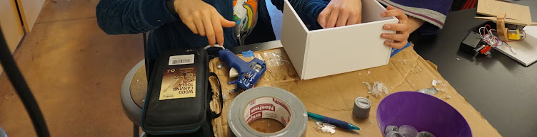
Throughout our project, we learned many things about the process of creating a functional structure. We made multiple models so that our final draft would be fairly easy to create and we would be pleased with our results. One of the models we made was a 3D printed model. By making a version on TinkerCad, we expanded our knowledge on how to build things on this platform. None of us knew how to actually print anything, so we sought assistance from a classmate and learned the art of 3D printing. We also learned about different tools and hardware pieces that were necessary for our project. For example, we learned how to use the circular saw and how to use a drill on a small piece of wood.
Within our time constraint, we could not finish our project but made the most of what we were able to get done. If we had more time we would complete it, doing things such as: cutting out doors, one for poultry and the other for human hands, creating runners and wheels to enable the floor to be a drawer for easy cleaning access, etc. Sadie intends to do this later in her free time. Even though we could not complete these elements of the project, we did plan them out. In our models, we included these. We also would have made roosts from strong sticks that we found in Maddy’s yard.
If anyone is looking to do this project, or one similar to this, such as building a dog house or other small structure, we would recommend creating accurate models that you can refer to when making the actual version. We did this and it helped a lot. Also, from our unavoidable mistakes, we learned that it is good to have your materials at the start so you know what you are working with.
If you are thinking of doing this project, it is good to keep in mind that it cost us about $64.97. Here is a link that shows in depth ways to start building a coop, link.
Measuring the wood.
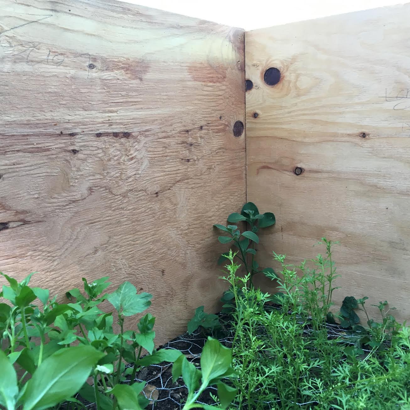
The inside of our project.
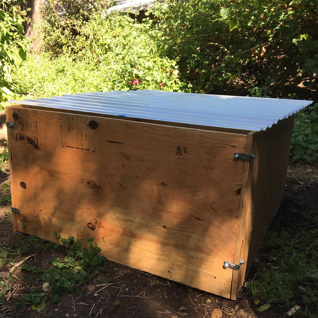
The bottom floor, outside of the coop.
Brainstorming the design.
Labels:
3D model,
7th grade,
Birds,
Chicken Coop Basement,
Chickens,
Coop,
maker faire,
Wood
Algae Lamp: Cole & Rafa 7C
We decided to make an algae lamp. Now, what is this you might ask? Well,
an algae lamp is a container with algae and water that uses photosynthesis and carbon dioxide to power itself. The lamp is able to capture carbon dioxide and sunlight, and form it into an algae battery to power the lamp and light it up. The lamp not only doesn’t use electricity and doesn’t produce carbon dioxide but instead does the opposite. The lamp takes in carbon dioxide, and then converts it into oxygen, just like trees. This new and incredibly great energy source could have a serious impact on the future world. We could use algae in the future to power cars, planes, etc. Instead of killing our environment, we'd make it better. We were inspired to do this project because we found it incredible that we have created an all-new energy source that could be used to help our world’s climate drastically in the future. It also interested us that we could light up our streets with only algae, and be helping our world as well. One challenge we faced was figuring out how the algae would connect with the lamp to make a sort of circuit for them so the light and carbon dioxide can pass through and let out oxygen, to start the cycle and charge the algae battery. The answers are not clear to the public yet, but we’re catching on. If we had more time, I think we could have figured it out. If we had advice for other people, we would tell them everything we learned, and how you could go off from what’s available, and try and piece things together to solve it. This project didn't cost anything yet because we got the algae naturally from Aquatic Park, and weren’t able to finish it with the time we had.
http://www.nbcnews.com/id/34149776/ns/technology_and_science-future_of_energy/t/paper-thin-batteries-made-algae/#.XOV_Io7Yr8khttp://www.nbcnews.com/id/34149776/ns/technology_and_science-future_of_energy/t/paper-thin-batteries-made-algae/#.XOV_Io7Yr8k
https://inhabitat.com/living-microalgae-lamp-absorbs-co2-from-the-air/
http://sustainable-nano.com/2015/03/03/algae-lamps/
http://b4tea.com/information/diy-algae-powered-lamp-how-to-make-it-at-home/
Making a Duct Tape Pencil Case
In this project, we were working to make a duct tape pencil case. We were going to use the pencil case, but because of a misunderstanding we lost it. Our inspiration for this project was that we didn't have a pencil case and we lose our pencils really easily, so we thought it would be good to make a pencil case.
The biggest challenge for us was making four sheets of double sided duct tape sheets. Due to the fact that when we touched duct tape it stuck to us, combining two sheets of duct tape was extremely difficult and annoying.
When making a duct tape pencil case, we learned that it’s not as easy as it looks. Duct tape is really sticky and when you accidentally get two pieces of duct tape stuck together, you can’t get get it unstuck.
If we had more time, we would make a cleaner looking pencil case and we would make it into a supreme pencil case.
If you are able to be patient and calm, this project will be 100 times easier. Also, you need to get the right materials.
Estimated cost; 17.77
We lost ours, so here is a picture from google:
Here is the book we used on Amazon: https://www.amazon.com/Tape-Make-101-Duct-Activities/dp/1438001355/ref=sr_1_2?keywords=duct+tape+book&qid=1559605689&s=gateway&sr=8-2
Storage Unit for the Girls Bathroom
For our maker fair project, we made a storage unit for free hair ties, pads, and tampons for the girls' bathrooms. We wanted to make these basic supplies easily accessible for everyone and didn’t think it was fair that girls had to pay for pads and tampons at a school. Also, who brings money to a bathroom at the passing period? Also, we decided it would be fun to add hair ties to the mix, although it’s not an absolute necessity, it is definitely nice to have some easily accessible in case you need to put your hair in a ponytail or get your hair out of your face in PE.
Some of our challenges included figuring out how to build the shelving units, how tall were they going to be, if they were going to have three or two compartments, and what to put in them. Another challenge was figuring out how to attach the different containers together—we weren't sure whether to use hot glue, drills, or wire. Another challenge was that the string we were using to tie the three baskets together was not stable enough. We ended up using lanyard string, though I'm sure that if we had more time we could have found an even better alternative.
We learned that when measuring wood you must take how thick the actual piece of wood is into account. We also learned how to safely use a jigsaw to cut wood. Finally, we learned the importance of measuring before you cut your materials.
Our next steps will be to talk to the head of school and ask if we can instal out shelving units into the girl's bathroom. Also, to actually finish both units.
If you do this project you should start off getting the measurements and design down before even thinking about building. Like the Russian proverb says "Measure seven times, cut once."
Depending on the materials you specifically use (different brands, shops, etc…) it should cost around $56 to start off. Ongoing, this specific project requires a steady flow of refills for it to be useful. The cost can also vary if you supply something besides hair ties, such as deodorant wipes.
We didn’t use any outside sources we just had the idea and got to work!
Overall this was a really fun, useful, and rewarding project that anyone can do.
Re Designing the Black Pine Circle School Garden's Watering System By: Maxime C and Kea M
Redesigning the Black Pine Circle School Garden Watering System
Estimated Cost of Project:
1 garden bed: $20
5 garden beds: $30
For the Black Pine Circle Annual Maker Faire, we designed and built a garden watering system. Our project
involved trying to improve the way our BPC school garden was being watered. It started on the basis of realizing
the garden wasn’t always being watered enough. We soon realized that this was because the students and
teachers didn’t have time to do it, and most folks didn’t know how much water each plant needed. In an attempt
to help water the garden correctly and thoroughly, we developed a system targeting each of these problems.
In the beginning, we were thinking of using an automated motorized pump to pump water through tubes to the
plants. With this design, we ran into problems almost as soon as we started. We realized that it would be very
difficult to set up a pump to water the plants, because we didn’t have a reliable source of electricity outside.
Without electricity, we had to make a system that used some sort of water tank that branched out into separate
tubes planted on spots near trees or plants in need of water. Thus, to get around our time and material
constraints, we decided to use a water bottle, a syringe, and a few tubes to water the garden.
First, we screwed a syringe to a water bottle; we used this to create the pressure that would pump the water
out our bottle into the tubes. Then, we tested it’s watering capabilities by placing each tube near a plant. We
started pumping. The pressure kept the water going, and we kept pumping the water, and watering the garden.
out our bottle into the tubes. Then, we tested it’s watering capabilities by placing each tube near a plant. We
started pumping. The pressure kept the water going, and we kept pumping the water, and watering the garden.
Throughout this process, we learned many things. The first is that, for anyone who might try this project,
it is always better to make a thorough model on paper before actually building a physical model. This gives
you the option for error without the risk of breaking a final model while trying to improve it. Another thing
that we learned that really interested both of us was the Siphon Principle of the flow of liquid through tubes.
This principle dictates that liquid can be pulled uphill if the end of the tube is lower than the start, much like this:
Unfortunately, this projected was a prototype, and was scaled down to a much smaller size. In reality, it would
be cool to set up a similar plant-watering system that had a similar, but more durable, metal tank that branched
through tubes to water various plants. Except: the tank would be a lot bigger, the tubing would be longer, and we
would use an automated valve system to minimize human labor. Altogether, we hope this project can have a
meaningful impact on the BPC garden, as well as others.
To Buy Materials:
Resources:
Tilda and Amelia's 2019 Maker Fair Blog Post
Our project was to make a flashlight in an Altoids tin. We wanted to learn about circuits and how they work. Our inspiration for our project was to make an accessible light source. One challenge we had was that we were new to circuits and needed to learn about them to understand our project. We learned about how circuits work. It took us a long time to figure everything out so if we did this a second time it would not take as much time. If we had more time we would try to make the flashlight, solar powered or make it easy to recharge the battery on a solar panel, so we could use a more sustainable energy source. Some advice we would give to others is to really research what you are doing before you get too far in. An estimated cost of our project if we had to buy everything except for the tools, would be about 10 dollars. This is a really cheap project that anyone can do if you have the knowledge, tools, and time. This is the tutorial we used. It did not explain how to solder the circuit so we had to get help.
Garden Cork Board
Hi, we are Quincy and Juliana for our School Maker Faire project we have chosen to redesign our school garden board into a garden poster board where we took a roll of cork and attached it to the board so people can write on a post-it nice things and pin them up on the board. We decided to do this project because we thought that since there was an empty space in the garden, why not make it useful and fix it up.
One of the challenges was that we got cork board so you would be able to hang stuff on it, but the cork board wasn’t as thick as we thought so we had to push in the pin harder and it surprisingly fit but it’s still not very secure we will work on that better.
In this process we learned that you can’t guess measurements in science and there is always something wrong with the project, you have to measure everything and make sure it is all equal. If we had more time we would have made a sort of roof, for the board since the cork board isn’t waterproof and it’ll mold if it gets wet but we weren’t sure how to make it and we didn’t have enough time. I think if we had any advice we would say get more than one roll of the cork board so it would be able to go through the whole thing and be able to stick, also measure everything.
The cost of the whole project would be 15.00$. https://docs.google.com/document/d/1qFCv03odS2FsTucVePr8M4Ih_nf7xCmhC1foa6IrXnQ/edit
Upcycled Fashion
The objective of our project was to reuse old clothes to make new “trendy” clothes. Our inspiration was seeing people throwing away perfectly good clothes when could just easily upcycle it, for example; when someone “throws away” a dress they could just make it into a top or/and a skirt.
One challenge we faced was not having clothes for the project. Since we didn’t want to spend money on the clothes because it would defeat the purpose of our project, we asked the people at our school if they had spare clothes they either don’t wear or don’t need anymore to bring it in, we also brought in some of our old clothes to upcycle.
In the process of our project we learned how to hand sew and how to manipulate the old clothes into new clothes. If we had more time, we would definitely upcycle more clothes and reach for bigger goals for the clothes we chose. If you do choose to do this project, make a plan for the things you’re going to upcycle, it’s better to see if you can improve on something before you start and mess it up and have no way of fixing it.
0$ spent on materials
3 hours spent on this project.
Tutorial video: https://www.youtube.com/watch?v=XnOdvk_1NBI
Avengers Infinity War Board Game: Infinity Board by Evan and Nora
Our project is a Avengers board game, our objective was to make a fun and cool board game for many ages. We were inspired by the move Avengers: Infinity War because we both really like it One challenge we faced was that it was really hard to make good circles but we overcame that when we got a protractor. We learned that you won't have much time and you want to give yourselves as much time as possible. If we had more time we would make our own pieces and not just use legos for the pieces. When doing Maker Faire, you should choose a project that is not very hard and save the hard projects for masterworks our maker faire project costs about $65.72 because of all the legos, other than that it costs nothing. Our outside resource was Avengers: Infinity War here is a link: https://www.imdb.com/title/tt4154756/
Subscribe to:
Posts (Atom)


